
Richard Loong Cheng Jun
Year 4 Computer Engineering
A0233496X
4. Software Development
Quick Links:
4.1 Scope of Work
As the main software developer of the team, my scope of work can broadly be described as the following:
- Create data structures to optimise the use of the onboard data storage
- Select electrical connectors to interface with the parent satellite
- Implement the necessary protocols to enable communication with the parent satellite
- Integrate software from the rest of the team into a single software package
- Design the testing setup and procedures for qualification
4.2 Design Objectives
The main objectives of my part of the project include:
- Storing experiment data in the payload’s onboard storage
- Reading data from the payload’s onboard storage
- Transferring data from the onboard storage to the parent satellite
- Receiving data from the parent satellite
- Handling commands received from the parent satellite
4.3 Design Requirements
The primary design requirement for my part is to ensure that our payload can be integrated with the parent satellite. Therefore, the specifications I have to meet are entirely dependent on our rideshare partner.
At the time of writing this report, our team does not have a confirmed rideshare partner yet. As such, there is no finalised list of specifications. However, we do have a technical partnership with In-Space Missions, which is a subsidiary of BAE Systems, and their Faraday Dragon program.
Through this partnership, I have access to some of the specifications and documents for the Faraday Dragon spacecraft such as their Payload Integration Emulator (PIE) user guide and their Interface Control Document (ICD). Therefore, I am basing many of my design choices on the Faraday Dragon spacecraft’s integration requirements.
4.4 Design Choices
4.4.1 Data Frame
Experiment data will be stored in the 32kB FRAM of the primary MCU. The actual experiment duration will depend on our parent satellite, but for development purposes, I am assuming the following mission parameters:
- 60 min total experiment duration
- 01 min interval between readings
Each experiment reading will be stored as a single data frame.
| Epoch Time | Particle Count | Error Count #1 | Error Count #2 | Experiment Data #1 | Experiment Data #2 |
|---|---|---|---|---|---|
| 4 bytes | 4 bytes | 2 bytes | 2 bytes | 256 bytes | 256 bytes |
| signed int | unsigned int | unsigned int | unsigned int | byte literals | byte literals |
4.4.2 Electrical Interfaces
2 different physical interfaces are being developed that can be toggled between before launch in order to accommodate possible rideshare requirements. A jumper will be used to select between the two interfaces. The unused interface will be electrically disconnected from the rest of the payload.
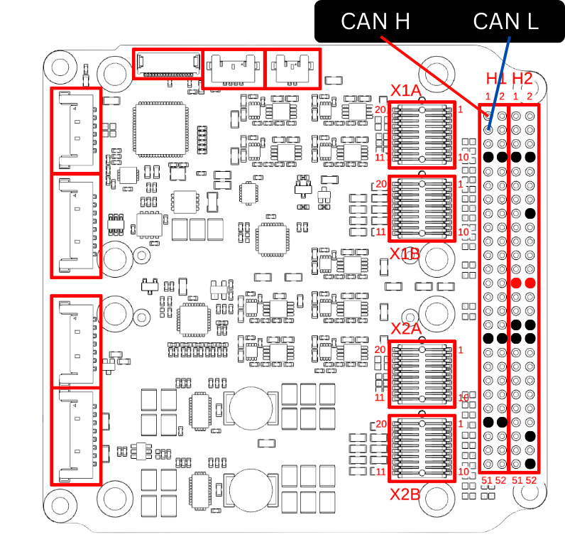
PC104 Pinstack
This is the 104-pin header that can be commonly found on cubesat components. There is no standard pinout for this header so the “manufacturer default” pinout from Gomspace products is being used:
| Connection | Pin |
|---|---|
| LV 5V | H2 Pin 25 |
| LV GND | H2 Pin 31 |
| HV 5V | H2 Pin 26 |
| HV GND | H2 Pin 32 |
| CAN H | H1 Pin 1 |
| CAN L | H1 Pin 3 |
This pinout is subject to change depending on rideshare specifications.
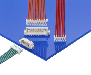
Molex Picoblade
For rideshares without the PC104 pinstack, the picoblade connector will be used. The picoblade connector supports up to 2.0A per connection and has flown on previous spacecraft. The picoblade connector is also the primary connector used during development and testing of the payload due to the ease of connecting and disconnecting a single connector as opposed to the PC104 pinstack.
4.4.3 Communication Protocol
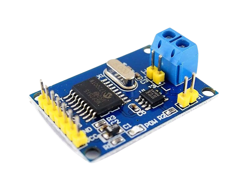
CAN is being used as the layer 2 communications protocol. It is widely used and is one of the protocols used by the Faraday Dragon rideshare. The primary MCU (ZSOM) does not have any onboard CAN hardware, so an external module is needed.
The CAN Controller is the MCP2515 and the CAN Transceiver is the TJA1050. There are many software libraries available that support these two chips. The CAN Controller connects to the SPI of the primary MCU.
While the TJA1050 is used during the development process because it is readily available on the same module as the MCP2515, it was replaced by the TCAN334RD on our final PCB. This is because while the MCP2515 can run on both 5V and 3.3V, the TJA1050 can only run on 5V and uses 5V logic levels. Thus the transceiver was changed to a 3V3 one for reliability. The TCAN334RD shares the exact same pinout as the TJA1050, so no changes to the PCB were needed. Furthermore, these was no need to adjust the software since the TCAN334RD does not directly interface with the microcontroller.
4.4.4 Communication Protocol (Layers 3+)
Cubesat Space Protocol (CSP) is used in the Faraday Dragon spacecraft. However, since we have no confirmed rideshare partner, we have opted not to implement CSP as there is no readily available package for microcontrollers.
Instead, a custom protocol that is simpler in implementation has been developed.
4.4.5 Payload Interface Emulator (PIE)
For testing, a Raspberry Pi 4B with the Waveshare RS485 CAN Hat was being used to emulate the Onboard Computer (OBC). However, the CAN Hat began malfunctioning during development, causing it to be unable to send CAN packets.
Thus, the CAN HAT was replaced by the Waveshare USB-CAN-A. It allows any device with a USB port to emulate the OBC. For ease of development, only devices running Ubuntu-based operating systems were used.

4.5 Custom CAN Protocol
The base CAN frame format has an 11-bit identifier and a 64-bit data field. The frame identifier is used to indicate message priority as well as message purpose. All frames with the same purpose (i.e. payload #1 data frame) should have the same identifier. CAN Frames also are not necessarily received in the same sequence that they are sent in.
To ensure that data is received properly, a custom protocol has been created. The payload controller only receives frames with an identifier of 0x010, filtering out all other frames. All frames originating from the payload controller have the identifier 0x011. These identifiers can be changed later as needed for integration with the parent satellite.
Command frames have the following structure:
| Byte 0 | Byte 1 | Byte 2 | Byte 3 | Byte 4 | Byte 5 | Byte 6 | Byte 7 |
|---|---|---|---|---|---|---|---|
| Command ID | Parameter A | Parameter B | Unused | ||||
The following commands are available:
| ID | Command | Param A | Param B | Description |
|---|---|---|---|---|
| 0x01 | Clear FRAM | Overwrites all bits in FRAM with 0 | ||
| 0x02 | Dump FRAM | Dumps the full 32kB FRAM via the CAN interface | ||
| 0x04 | Dump partial FRAM | Dumps the first 512 bytes of FRAM via the CAN interface for debugging purposes | ||
| 0xAA | Update RTC | Epoch Time | Synchronises the Payload Controller’s RTC with the parent satellite’s timekeeping service | |
| 0xEF | Fill FRAM | Overwrites all bits in FRAM with 1 | ||
The following response frames from the payload controller are available:
| Response Type | Byte 0 (Type Identifier) | Byte 1 | Byte 2 | Byte 3 | Byte 4 | Byte 5 | Byte 6 | Byte 7 |
|---|---|---|---|---|---|---|---|---|
| Command ACK | 0x01 | Command ID | Command Status Code | Unused | ||||
| Data Frame | 0x02 | Memory Address | Unused | Memory Data | ||||
| Error Frame | 0xEE | Error Code | Unused | |||||
4.6 Implementation and Testing
4.6.1 Emulator Setup
Any device running Linux with an available USB port can be used as the emulator. Plugging in the USB-CAN-A into a USB port should make the device available as a virtual device /dev/ttyUSB0. The number might change depending on the USB port used. Once the virtual device is detected, it is ready to use.
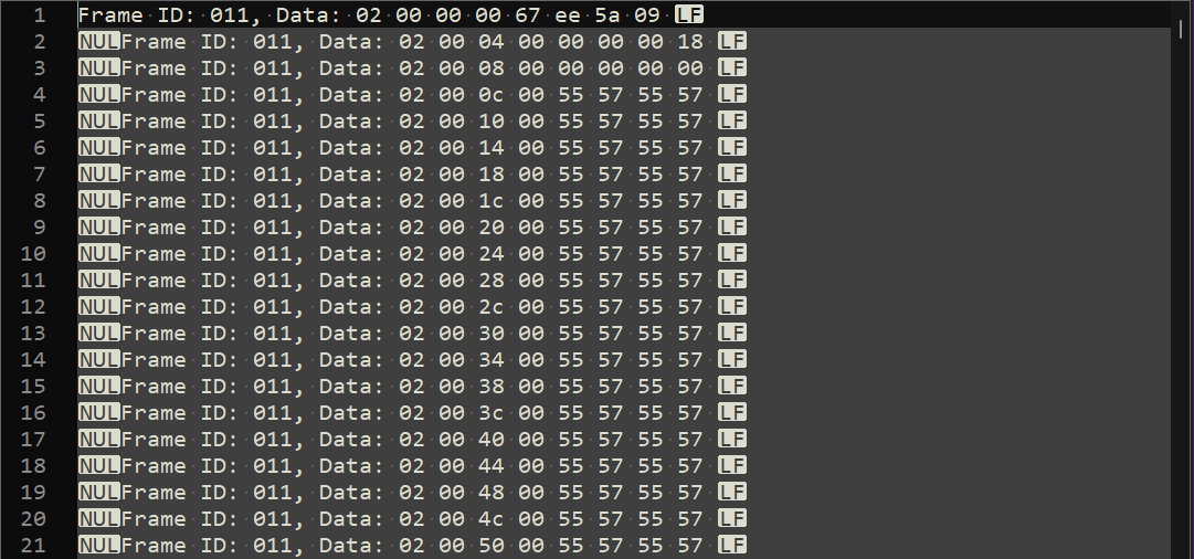
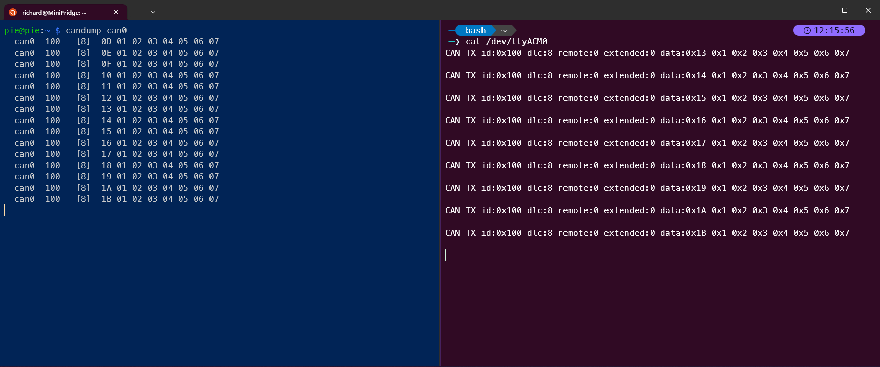
4.6.2 Serial Data transfer via CAN
CAN frames were successfully sent and received between the PIE and the primary MCU. The
AA_MCP2515 library was used on the primary MCU as this library allows for easier customisation of pinouts and changing frame IDs.
4.6.3 Implementation of RTC
A time-keeping service is required for our experiments to have access to accurate time information. Timekeeping data can usually be obtained from a parent satellite via a heartbeat signal or the satellite’s timekeeping service, but we do not have a confirmed parent satellite. Thus I decided to use the Real-Time Clock (RTC) available in the SAMD21 microprocessor as the primary timekeeping system.
The ZSOM does not have any onboard battery to ensure the RTC could run continuously, so the RTC will be periodically synchronised with the parent satellite’s timekeeping service to prevent the timekeeping from becoming inaccurate after a power off.
The RTCZero library by Arduino is used to control the RTC.
4.6.4 Command and Control (C&C) via CAN
C&C is implemented using an interrupt service routine (ISR) that is triggered by the CAN controller. The ISR is triggered when a CAN frame is received. The ISR will then read the frame and update a global variable with the command ID. The main loop will then check the global variable and execute the command. The ISR will ignore commands if the previous command is still being executed.
For development and testing purposes, an emulator program was written in C++ to send and receive CAN frames. It is able to send each of the commands listed in Table 4-3, and is able to receive and save the response frames from the payload controller as a text file. The emulator can be run from the command line, or as a (Terminal User Interface) TUI application. The CLI version is used primarily with bash scripts for long duration tests, while the TUI version is used for manual testing.
The emulator is able to run on any device with a USB port and an Ubuntu-based operating system.

4.6.5 Integration of Software
Each individual team member is responsible for writing their own software for their respective subsystems. Once the proof of concept is complete and has been tested, each piece of software is handed over to me for integration into a single software package. This requires adapting the software to resolve any conflicts between the software, such as pin conflicts, and ensuring that the software can run on a single microcontroller. Some software may also need to be rewritten to ensure that it can run on the SAMD21 as it has a different architecture from the ATmegas used in more common Arduino boards.
Quality of life features were also added to the software for easier debugging and testing. These include:
- Compiler flags to enable or disable debugging features
- LED indicators to show the status of the payload
- Separation of the code into multiple files to improve readability and maintainability
The payload controller software can be found on GitHub.
GM Counter
The GM Counter is a simple program that counts the number of particles detected by the GM tube. The signal conditioning circuit amplifies the signal from the GM tube and converts it into a digital signal. The signal pin will be pulled low when a particle is detected, triggering an interrupt that increments a counter. The counter is read and reset every minute.
Changes to the GM Counter program include:
- The use of a timer interrupt to read the counter every minute instead of using the
millis()function. This is to ensure that the counter is read at a consistent interval, and to reduce the load on the main loop. - Removal of the
delay()function to prevent blocking the main loop. Previous versions of the program useddelay()to control the debug LED that indicated a detection. This was changed to using the main loop to reset the state of the LED. - Addition of a debouncer to prevent false positives from the GM tube. The GM tube can produce an unstable signal when its voltage drops too low, causing it to trigger multiple interrupts. The debouncer will ignore any interrupts that occur within a certain time period after the first interrupt. This time period is set to 10ms.
- Integration with the FRAM library to allow for the GM Counter to store the count in the FRAM.
SRAM Experiment
The SRAM experiment is a program that tests the SRAM of the two ATmega32U4 microcontrollers. The program reads the SRAM and compares it to a known value. If there is a discrepancy, the program will increment a counter. It also copies a sample of the SRAM. The SRAM experiment program runs in parallel with the GM Counter program.
Changes to the SRAM experiment program include:
- The use of a timer interrupt to read the SRAM every minute instead of using the
millis()function. This is to ensure that the SRAM is read at a consistent interval, and to reduce the load on the main loop. - Addition of a delay to prevent the program from reading the SRAM too quickly, which can cause the handshake signal to be missed.
- Integration with the FRAM library to allow for the SRAM experiment to store the count and samples in the FRAM.
4.6.6 Utilities and Tools
A set of utility scripts was developed in Python to help with the processing and analysis of the data gathered by the payload. These scripts convert the hexadecimal data into human-readable CSV files.
1-dump-to-fram.py
This script takes the text files generated by the emulator and converts them into a csv file that contains all the data stored in the FRAM along with the memory address of each word.
2-fram-to-csv.py
This script takes the csv file generated by the previous script and converts it into a csv file that has the data in a more useful format, with the time and the data separated into different columns.
3-merge-csv.py
This script takes the csv files generated by the previous script and the data from the thermal testing chamber and merges them into a single csv file. This is useful for comparing the data against the environment temperature.
4.7 Testing Setup and Procedures
4.7.1 Onboard Testing Features
The payload controller has a number of onboard testing features that can be used to test the payload in a controlled environment such as a thermal vacuum chamber. These features include:
- Clearing the FRAM (overwriting all bits with 0)
- Filling the FRAM (overwriting all bits with 1)
- Dumping the FRAM (reading all bits from the FRAM)
These features allow for the payload to be tested in a controlled environment and to ensure that the FRAM is functioning correctly.
4.7.2 Individual Test Cycles
An individual test cycle is a series of steps taken to evaluate the functionality of the FRAM on the payload controller. It is designed to be run in a controlled environment such as a thermal vacuum chamber. The test cycle consists of the following steps:
- Dump the FRAM
- Fill the FRAM with 1s
- Dump the FRAM and check that all bits are 1
- Clear the FRAM
- Dump the FRAM and check that all bits are 0
This ensures that all bits in the FRAM are functioning correctly and can be read and written to correctly. The test cycle can be repeated as many times as necessary to ensure that the FRAM is functioning correctly. This test is conducted at one hour intervals during environmental and long duration testing.
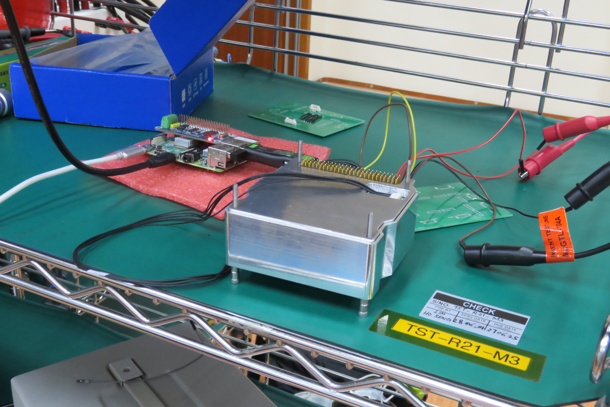
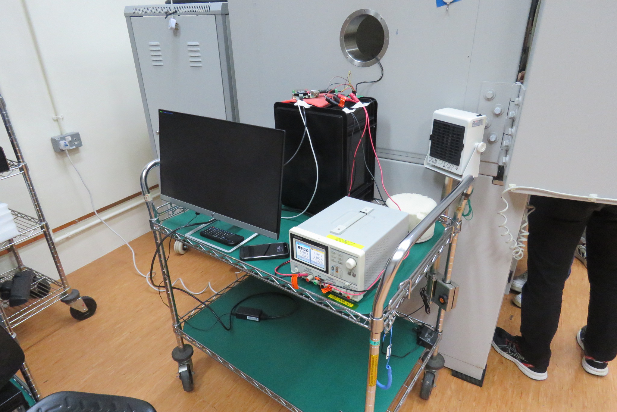
4.7.3 Testing Setup
The minimal testing setup consists of the payload and the emulator. The payload controller is connected to the emulator via the CAN interface, along with two 5V and two GND connections, one for the High Voltage (HV) PCB and one for the Low Voltage (LV) PCB. For most of the tests, the emulator was a Raspberry Pi 4B with the Waveshare USB-CAN-A. crontab is used to schedule a bash script to run every hour. The bash script runs the emulator program starts a test cycle. The outputs are saved to a text file for later analysis.
4.7.4 Long Duration Testing
Before sending the payload for environmental testing, a long duration test was conducted to ensure that the payload was functioning correctly over an extended period of time. The payload was powered on and a test cycle was run every hour for 72 hours.

The payload was able to run successfully for 19 hours before the raspberry pi power supply began malfunctioning, causing the payload to behave erratically. The power for the payload was supplied by the Raspberry Pi, which was powered by a 5V 4A power supply. Due to the power supply issues, the test was unable to run for the full 72 hours.
After replacing the power supply for the payload with a benchtop power supply and the Raspberry Pi power supply with an iPad charger, the payload was able to run without any issues. The payload was able to read and write to the FRAM without any issues, and the GM Counter was able to count particles without any issues.
4.8 Environmental Testing
We were able to use the shaker table and thermal chamber at ST Engineering to conduct environmental testing on the payload. The payload was subjected to a series of tests to simulate the conditions it would experience in space. These tests included:
- Vibration testing
- Thermal testing
4.8.1 Vibration Testing
Vibration testing was conducted to simulate the conditions the payload would experience during launch. The payload was subjected to a series of vibrations at different frequencies and amplitudes to identify the natural frequency of the payload.
The payload was not powered on during the vibration testing. After the testing was completed, the payload was powered on and a test cycle was run to ensure that the payload was still functioning correctly. The payload was able to successfully complete the test cycle without any issues.
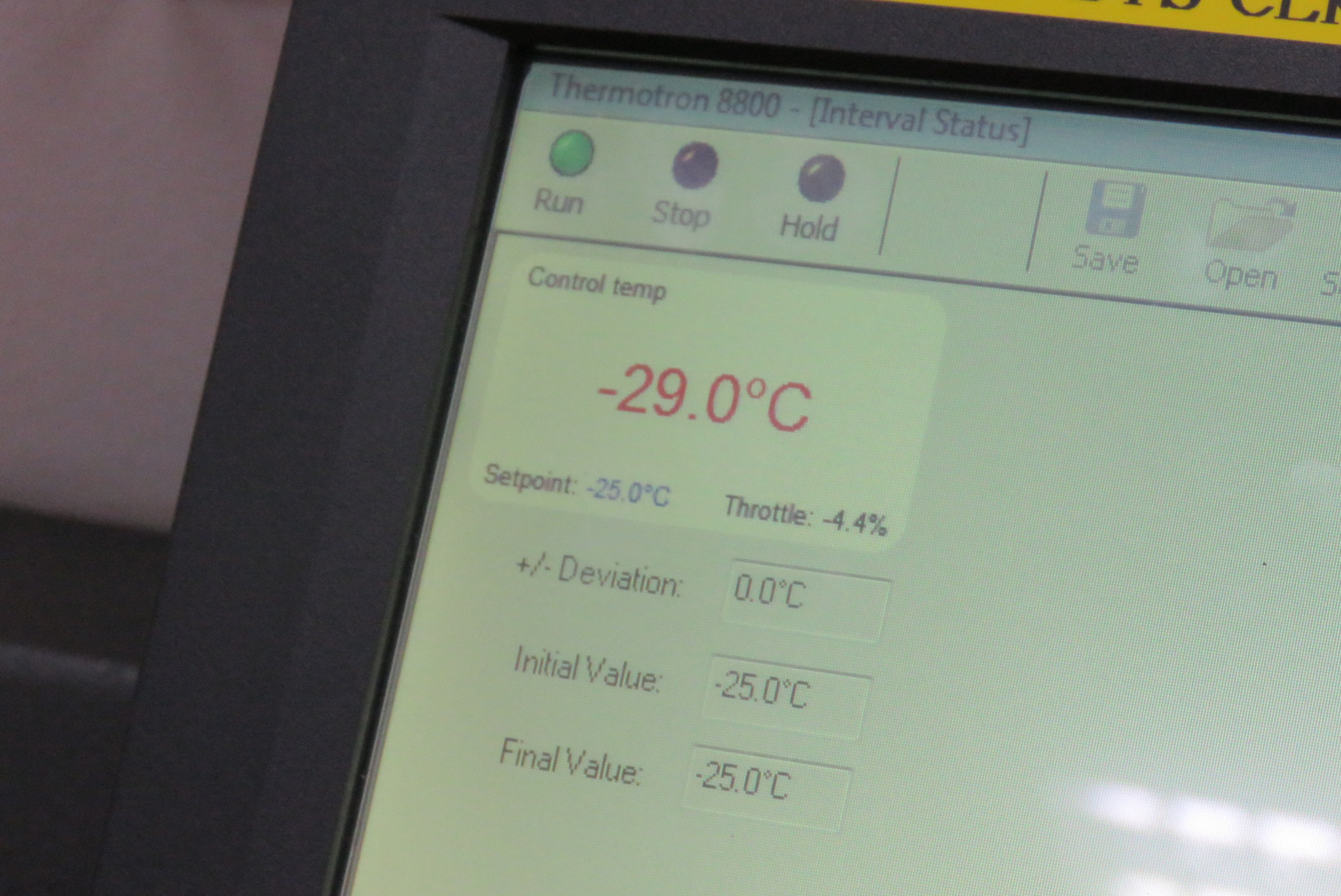
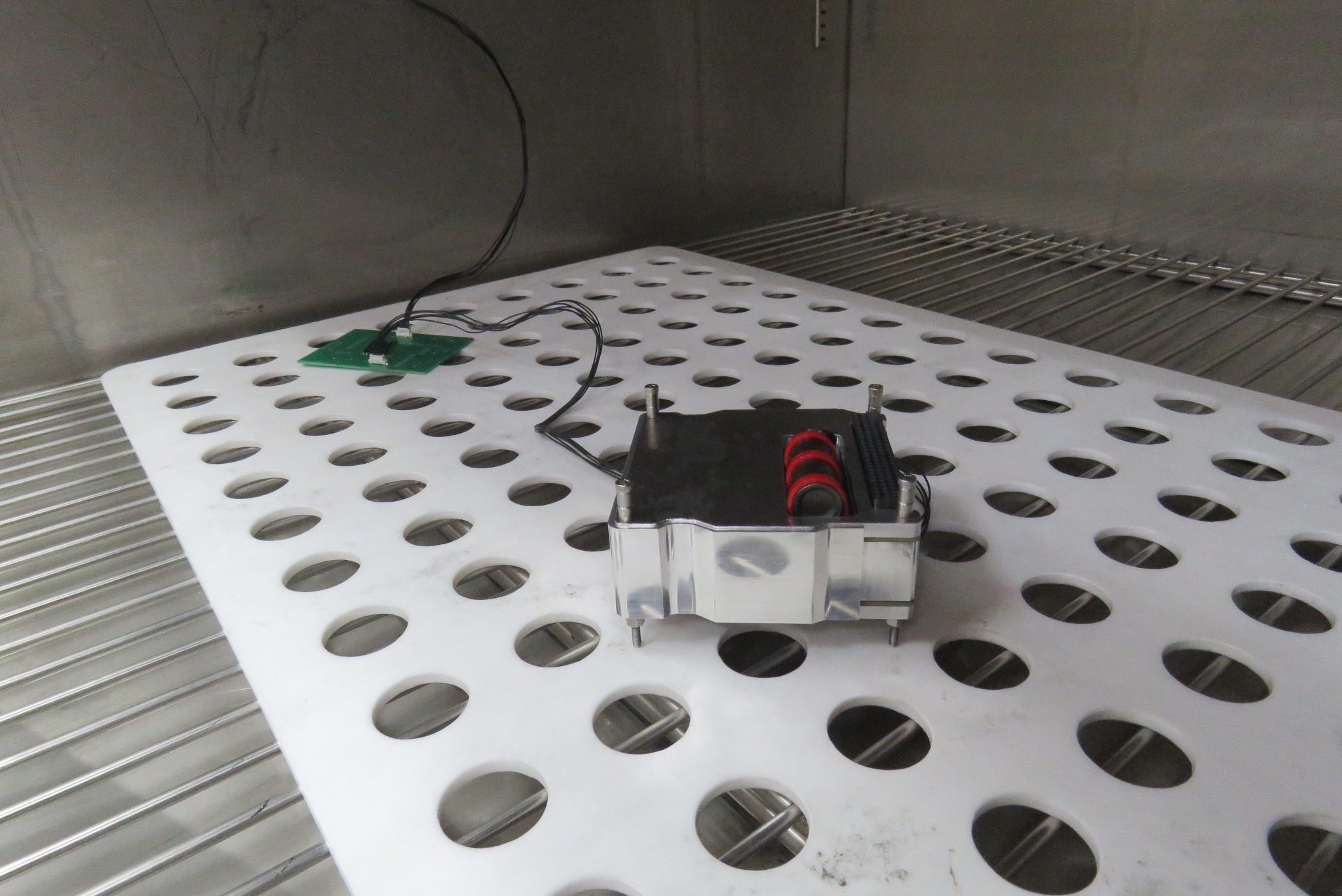
4.8.2 Thermal Testing
Thermal testing was conducted to simulate the conditions the payload would experience in space. The payload was subjected to a series of temperature cycles to identify the thermal limits of the payload. Each cycle would bring the temperature down to either -30°C or -25°C, hold that low temperature for 4 hours, transition to 70°C and hold for another 4 hours. It was subject to two cycles, taking over 16 hours to complete. The payload was powered on during the thermal testing.
The test cycles were run overnight. The payload was able to successfully complete the test cycle without any issues. The payload was able to read and write to the FRAM without any issues, and the GM Counter was able to count particles without any issues. The payload was able to successfully complete the test cycle without any issues. However, the testing equipment failed multiple times, requiring the test to be performed multiple times.
4.8.3 Test equipment failure
During the first attempt at thermal testing, the payload was able to read and write to the FRAM without any issues, and the GM Counter was able to count particles without any issues. However, the Raspberry Pi began malfunctioning at the 7 hour mark, causing the test data to be lost after that point. When we checked on the payload, the Raspberry Pi was powered on, but the data from the payload was missing.
Checking the system logs on the Raspberry Pi revealed that it had shutdown at the 7 hour mark, only powering back on just before we arrived at the lab, well past the intended 16 hour test. Further investigation revealed that the power supply was not providing enough current to the Raspberry Pi, triggering undervoltage warnings and causing it to behave erratically, eventually shutting down.
The power supply was replaced with an original Raspberry Pi 5V 4A power supply and the payload was powered on again. The Raspberry Pi seemed to be working correctly, so it was left to run overnight. The next day, the Raspberry Pi has a blinking power LED, indicating it was not able to power on. The power supply was replaced with the iPad charger that was used previously to check the system logs, which showed that the power supply had failed again.
The Raspberry Pi was replaced with a laptop and the payload was powered on again. The payload was able to read and write to the FRAM without any issues, and the GM Counter was able to count particles without any issues. This time, the test cycle could be completed without any issues.
4.8.4 Test Results
All three attempts at thermal testing showed that the payload was able to handle repeated exposure to extreme temperatures. The payload was able to read and write to the FRAM without any issues, and the GM Counter was able to count particles without any issues.
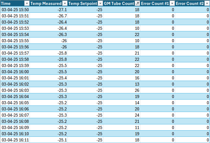
The data from the successfult thermal test was run through the three utility scripts to convert the data into a more useful format. The data was then merged with the temperature data from the thermal chamber to create a single CSV file that contains all the data from the test. The data showed that the payload worked correctly throughout the test, with little change in the GM Counter readings.
4.9 Conclusion
The payload controller has been successfully developed and tested. The payload controller is able to read and write to the FRAM without any issues, and the GM Counter is able to count particles without any issues in both normal and extreme conditions. The payload controller is able to communicate with the parent satellite via the CAN interface, and the payload controller is able to receive commands from the parent satellite. The payload controller is able to run for extended periods of time without any issues, and the payload controller is able to handle extreme temperatures without any issues.
However, the payload software still has further improvements that can be made. These include:
- More communication originating from the payload controller such as indications for a full FRAM
- Updating system parameters over CAN
Furthermore, steps have to be taken to integrate the payload with the parent satellite. Oncea rideshare partner is confirmed, the payload controller will be updated to meet the requirements of the parent satellite. This includes updating the communication protocol to match the parent satellite’s requirements, and updating the electrical interfaces to match the parent satellite’s requirements. The payload controller will also be updated to include any additional features that the parent satellite offers such as a timekeeping service or a heartbeat signal.