
Ho Wei Hao
Year 4 Electrical Engineering
A0240152X
2. Radiation Monitoring System
2.1 Jobscope
The scope of my work within the project consists of the following tasks:
1. Radiation Sensor Operations
The payload needs to monitor the radiation it receives as part of the mission. A radiation sensor has to be powered and its data read and stored.
2. High Voltage PCB Design
Custom PCBs have to be designed for the payload. Considering the high voltage lines, involved, they need to have sufficient clearance from the low voltage system. This prevents inference between the two systems that can break down the entire payload.
2.2 Design Specifications
Since the mission requires the payload to monitor the amount of radiation it experiences, I need a proof of concept to show that the radiation sensor can be integrated into the payload. Its design must meet the following criteria:
| Feature | Specification | Reasoning |
|---|---|---|
| Operating Voltage | 5V | Assumption of 5V provided |
| Current Consumption | <2A | Assumption of 2A maximum provided |
| Radiation Sensor | Detects alpha and beta particles | Monitor the particles responsible for SEE |
| Signal processing | Trigger microcontroller with signal | Ensure that radiation is correctly recorded by the microcontroller. |
| Microcontroller | Radiation-Hardened | Provide reliable data storage throughout the mission |
| High and low voltage clearance | Ensure voltage lines do not interfere with each other | Avoid compromising other systems on the same payload or satellite |
| Signal interference | Signals only travel through the signal line | Prevent unwanted noise in other lines |
2.3 Design Specifications
2.3.1 Microcontrollers
Design Choice
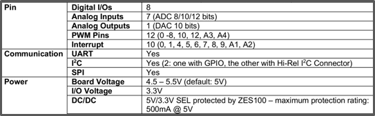
As specified in the design requirements, a radiation-hardened microcontroller was required to store data reliably. This will ensure that the mission results are reliable.
The ZSOM-M01 was considered because it can be programmed with the Arduino IDE, not only making it easily programmable but also interfaceable with the other chips we wish to experiment with.
Further analysis of the microcontroller’s available storage was conducted to further assure its suitability for the project. This is because as part of a radiation payload, components are to be exposed to high levels of radiation, increasing the risk of SEU occurring. A detailed comparison can be found in Appendix E.
FRAM was deemed suitable to store all the data due to its radiation-hardened status which reduces the risk of data corruption. Additionally, the proprietary EDAC code can correct any bitflips in the FRAM, further enhancing its data protection. The FRAM is also configured in Triple Modular Redundancy with radiation-hardened voters (Zero Error Systems, 2024b). This adds a third layer of protection for its memory contents, making it a suitable choice. The radiation-hardened test summary provided by Zero Error Systems can be found in the appendix.
Since the trustworthy Zero Error Systems meets the requirements of the mission, it has been chosen for the project.
Design Proposition
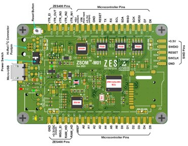
From Figure 2-2, either the A1 or A2 pin can be used for the signal input from the radiation sensor as it has interrupts attached. This allows the microcontroller to detect the unpredictable random arrival of the radiation signals.
Similarly, the D0 pin will be used to control the DC-DC converter due to its pulse-width modulation (PWM) output, since most converters require a PWM signal to control its high voltage output.
2.3.2 Radiation Sensors
Design Choice
Several radiation sensors were considered below. These sensors were chosen on their ability to detect the desired charged particles.
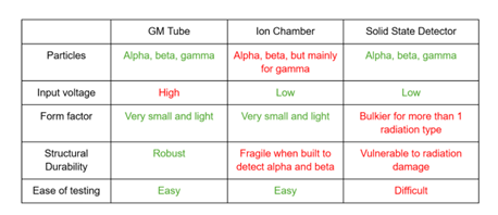
A more detailed comparison of the other sensors is in Appendix G.
Geiger-Müller (GM) tubes are preferred in our project to provide radiation data from desired particles that are responsible for SEE. It only requires simple electronics to provide high potential difference across its terminals and to read the signals it produces, making it easy to integrate. They are also considered a cheap relative to other sensors, but they have low energy detection efficiency when receiving high doses of radiation (Matsusada Precision Inc., 2024). However, it is sufficient as the project only needs to quantify the radiation received by the payload, and does not need comprehensive and high-resolution data. The GM tube is also chosen since the other two options are also more vulnerable to damage during space operations, causing a major risk of failure during the mission.
Design Proposition


The LND 712 is chosen for our purposes. It requires between 450 to 650V to operate, hence power can be supplied easily with a DC-to-DC converter, making it easy to integrate. The connections required are also very simple, requiring two resistors and a 50pF capacitor. This component, although being one of the largest components in the circuit, only weighs a mere 8g, therefore providing extra allowance on the mass budget for other purposes (LND. Inc., n.d.).
2.3.3 DC-DC converter
Design Choice
The chosen radiation sensor would require between 450 and 650V to operate properly. Hence, DC-DC converters that can provide up to 500V were sourced.
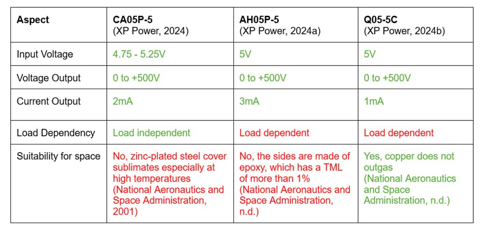
After testing all three converters, the CA05P-5 worked best. It is load-independent (XP Power, 2024), ensuring that it will output 500V regardless of the circuit load. This proves useful in designing the circuit, which acts as an open circuit in steady-state and is complex to account for its load. This is in comparison to the load-dependent converters, whose output dropped to around 300V which is insufficient for the GM Tube to ionize incoming radiation particles and operate normally.
The primary issue with CA05P-5 is that its covering is made of zinc-plated steel (XP Power, 2024). The zinc plating is known to sublimate in space, especially in high temperatures. For the proof of concept, the CA05P-5 will be used To validate the circuit design. However, sourcing for a more space-compatible alternative remains part of future work.
Design Proposition

The CA05P-5 expects an input of 4.75 to 5.25V and can return a range of voltages from 0 to 500 volts regardless of the output load. Its output current is 2mV, which is sufficient for the signal reading circuitry.
2.3.4 Circuit Layout
Reference was taken from a tutorial on Sparkfun on assembling the circuit components.
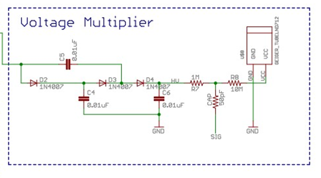
After designing the circuit, the GM tube receives less than 450V due to voltage drop across the 10MΩ and 1MΩ resistors. Although the high-voltage circuit is supposed to be an open circuit due to the GM tube, there is a small microcurrent flowing through the circuit. Hence the resistors were replaced with ones of lower value to reduce the voltage drop and supply the GM tube with sufficient voltage to operate
The eventual circuit is as follows:
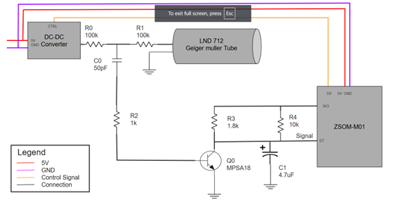
The circuit is made of the following parts:

Lowpass Filter (R1 and C0) to prevent signals from interfering with the source.
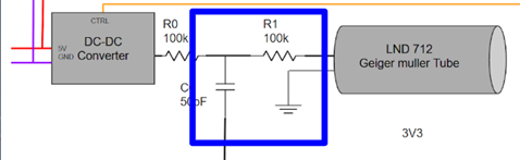
Highpass Filter (R0 and C0) to filter signals towards the microcontroller.
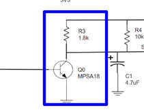
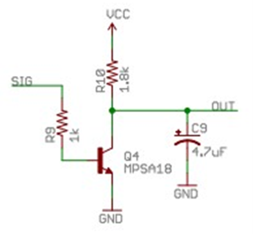
Current amplifier (Q0 and R3) to amplify the current of signals to be identified by the microcontroller.
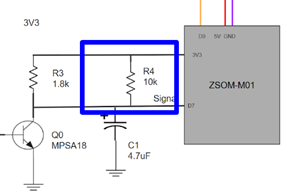
A 3.3V pull-up (R4) to bring the signal line to 3V3 if the line is floating.
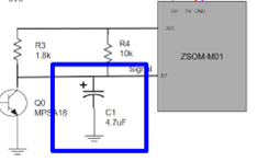
Lowpass filter (C1) to clean up signal for reading.
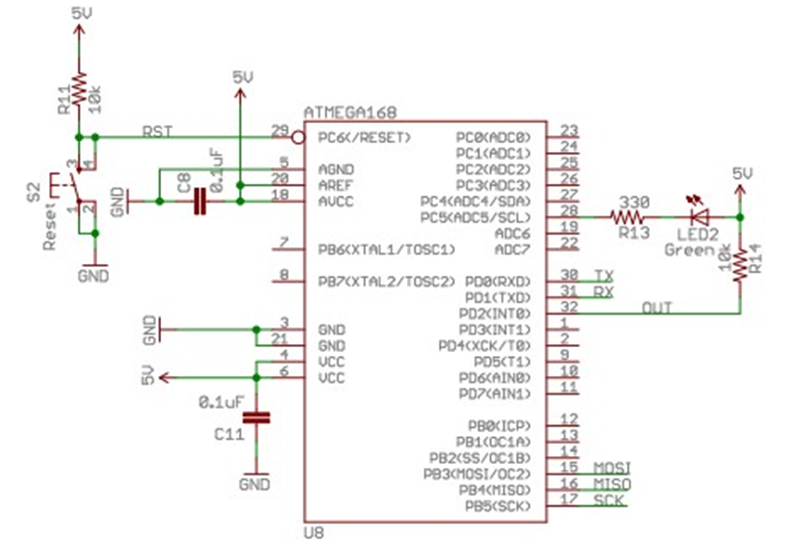
This circuit is accompanied by a simple code flashed in the microcontroller for it to detect the signals. The circuit can be found in the appendix C.
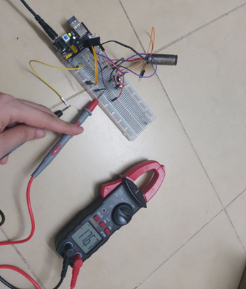
2.3.5 Results and Verifications
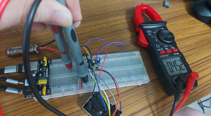
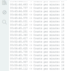
The microcontroller successfully detected the radiation signals from the GM Tube.
This proof of concept validated the following findings: Load-independent DC-DC converter provided reliable 500V that is sufficient for GM Tube operations Signal conditioning is sufficient, and the signal from the GM is detectable by the microcontroller. Following form this experiment, further optimizing the circuit components, especially R0, R1, and C0 is required before the custom circuit board can be designed and fabricated
2.4 Future work
Following the proof of concept, more work is required in the future to complete the project. This includes: Optimise and finetune the circuit components Calibration of GM Tube Procuring alternate DC-DC Converter High Voltage PCB Design Integrating GM Tube code and data into the software from software member Integrate with other electrical member Integrate with mechanical member