
Wang Mingchuan
Year 4 Mechanical Engineering
A0240129N
5. Mechanical
The mechanical requirements of the payload consists of 2 main parts: choosing and testing a radiation shielding material and designing the configuration of the payload.
5.1 Choosing a Radiation Shielding Material
The aim of this project is to test the effects of radiation on the electronic components and find a suitable material for shielding from SEEs. As such, we will need to choose a suitable radiation shielding material to protect against alpha particles, protons and beta particles which are the main sources of radiation in the VAB (Howell, 2018; Julien, n.d.).
There are many types of materials that are commonly used for radiation shielding, such as lead, gold and other high atomic mass materials. We choose some of the materials on the market that are known for their radiation shielding properties and rank them in a matrix table.
| Material | PEEK | PEEK infused with heavy atoms | Aluminium 6061 | Concrete | Lead |
|---|---|---|---|---|---|
| Price | 3/5 | 0/5 | 5/5 | 2/5 | 2/5 |
| Weight | 4/5 | 4/5 | 3/5 | 2/5 | 1/5 |
| Shielding Properties | 1/5 | 5/5 | 4/5 | 5/5 | 5/5 |
| Availability | 10/10 | 0/10 | 10/10 | 7/10 | 7/10 |
| Score | 18/25 | 9/25 | 22/25 | 16/25 | 15/25 |
We have chosen price, weight, shielding properties and availability as our factors to consider in choosing the material. Availability has a higher weightage as we are aiming to find a cheaper alternative to radiation hardening. If the material is not readily available, our results will have less impact on our stakeholders.
After considering all the common materials, we have decided to choose aluminium 6061 as it is available and suitable for space. PEEK and PEEK infused with heavy atoms are not very available and more on the expensive side. Concrete is not suitable due to its brittleness whilst lead is too heavy. In addition, space agencies are also trying to shift away from lead due to environmental and health regulations (Sampson, n.d.). A full breakdown of the properties of the materials can be found in Appendix B1.
5.2 Testing the Material
In order to quantify the shielding properties of aluminium 6061, we will be conducting an experiment to find out how the radiation shielding varies with changes in thickness. This aids us in choosing a suitable thickness for the shielding. In addition, ground data collected can help us to calibrate our GM tube and also serve as a reference for future data collected in space.
The experiment was conducted using two GM Counters and 3 aluminium boxes of thickness 2mm, 4mm and 4mm. The boxes are of different sizes and can be placed into one another, giving us effective thicknesses of 2mm, 4mm, 6mm, 8mm and 10mm. These thicknesses are chosen as they are the typical shielding thickness in CubeSats. The specifications of the GM Counter can be found in Appendix B2.
Readings were taken using the 2 GM Counters for 30 minutes, with one placed outside the box to measure the background radiation and the other placed inside the box to measure the radiation levels with shielding. It is then repeated by varying the thickness. The GM Counter outside serves as a control. The final result is plotted using the percentage drop in Counts Per Minute (CPM) of the GM Counter inside the box compared to the control GM Counter, against the thickness. A detailed methodology of how the experiment is conducted can be found in Appendix B3.
However, as we are unable to differentiate the different radiation particles using our GM Counter, we can only measure the overall effectiveness of shielding by the CPM.

From the experiment, there seems to be a linear relationship between percentage drop in CPM and shielding thickness. This suggests that the thicker the shielding, the better the shielding. As such, we should optimise the shielding as much as possible to lower the chances of SEEs.
Initially, we were expecting a plateau in the reading as we would expect alpha and beta particles to be blocked after a certain thickness (IMS Team, n.d.). However, there did not seem to be any plateau from the results other than the fluctuation at 8mm. This might be due to other radiations in the background, such as X-Ray and Gamma-Ray, which contributes to the counts detected. In addition, due to the random nature of radiation (Ojovan et al, 2019) and high fluctuations (GQ GMC-600 Plus Geiger Counter Radiation Monitor, n.d.) , the reading at 8mm dropped, despite averaging out the readings over 30 minutes. Even with a 10% error bar, it is still outside the trend. As such, more data has to be collected to build a comprehensive database, so that we can use the database to compare with data collected in space, and get a result for shielding effectiveness.
5.3 Configuration and Design of the Payload
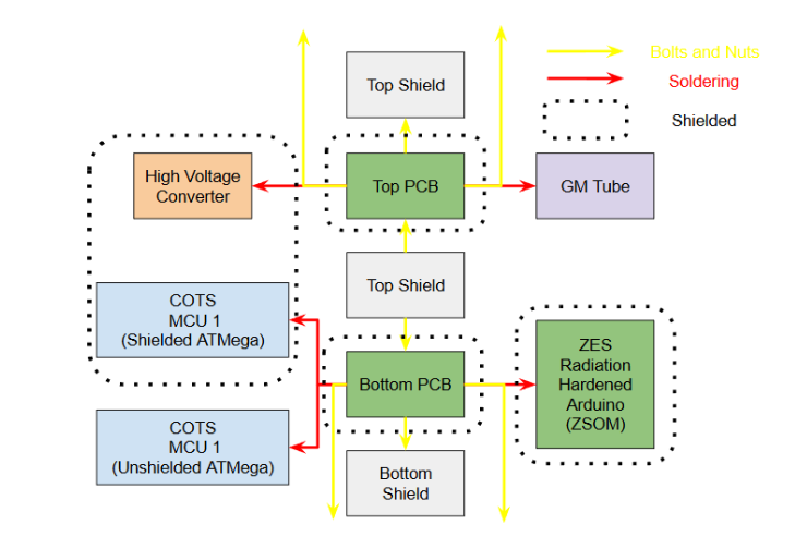
In order to optimise the design of the shielding and structure of the payload, many iterations of design were considered. The payload needs to accommodate all the electrical parts such as the PCBs, High Voltage Converter, GM Tube, ZSOM and the MCUs, whilst shielding the right parts. For our payload, the High Voltage Converter, COTS MCU 1, ZSOM and PCBs have to be shielded. In addition, the dimensions and weight of the payload has to fit within 0.5U and below 0.66kg, whilst ensuring all the materials are space suitable (NASA, 2024; Kelley & Jarkey, n.d.). Below is the mechanical architecture diagram of our 3rd and current design iteration.
Throughout our iterations, we have constantly updated our designs and improved on it.
For the first design iteration, all the electrical components on one side of the PCB. However, there was not enough space to accommodate all the components. In addition, the close proximity of components that are supposed to be shielded and not shielded makes the designing of the shielding unnecessarily complicated for manufacturing. This is especially for components such as the high voltage converter which has a height and placed very near to other components that are not shielded, such as the GM Tube. As we need to shield only the high voltage converter, there needs to be space in between these two components for the shielding and mounting. Optimizing the shielding to fit into this space will be difficult. In addition, if there are any changes made to the placements, the whole shielding has to be redesigned.
To accommodate all the components and also to streamline the shielding design process, the second design has the shielded and unshielded parts on different sides of the PCB. This makes space for all the components and we can have a one size fits all shielding on the shielded side as seen in Figure 4. For the other side where components have to be exposed, we can have cut outs on the shielding. However, having the high and low voltage components on the same PCB makes it dangerous, especially when the components are placed quite closely to each other. In addition, having all the components on 1 PCB makes it difficult for the two electrical team members to work on the project separately, as Sowmya is working on the COTS MCUs and ZSOM whilst Wei Hao is working on the GM Tube and high voltage converter. This reduces the efficiency.
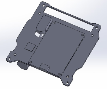
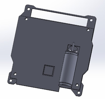
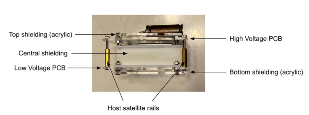
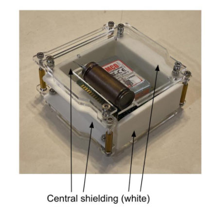
To resolve the safety issue and increase the efficiency, the third design was developed with 2 PCBs, one for low voltage and one for high voltage. The design is a sandwich structure where the shielded components are in between the PCBs, surrounded by a central shielding as shown in Figure X. The exposed components are on the outside of the 2 PCBs as shown in Figure X. The modularity of the two PCBs makes it such that they can be worked on separately before assembling together. However, more optimisation has to be done to place all the components safely from each other and also to fit the height of the payload within the 0.5U limit.
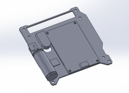
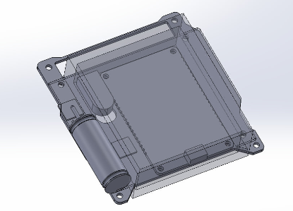
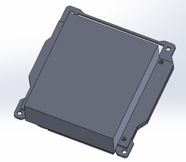
The CAD model of the current design can be found in Appendix B4, detailed specifications can be found in Appendix B5 and properties of the components used can be found in Appendix B6.
5.4 Future Work
Moving forward, more data regarding the effectiveness of shielding has to be collected to build a more comprehensive database. This will help in calibration of the GM Tube. More design optimisations have to be made to the payload to maximise shielding, optimise dimensions, weight and placements. Mechanical testing and simulations such as vibration, shock, thermal tests have to be done as well. More details regarding the future work can be found in the Future Work session.